Comparator Hysteresis Design Equations
A comparator is an electronics circuit which compares the voltage of a signal to a voltage reference. If the signal's voltage is greater than the reference, the the output of the comparator swings to the top rail, and likewise if it is less than, it swings to the bottom rail. Comparators are useful in converting analog signals into square digital signals.
hysteresis is often employed in comparators, and is useful in eliminated noise and glitches. With hysteresis a comparator has two voltage thresholds: a high threshold when the output is low, and a low threshold when the output is high. If the output is currently low, then the input voltage must swing above the high threshold, which is higher than the reference voltage, to make the output swing high. Likewise, when the output is high, the input voltage must swing below the low threshold, to make the output swing to the low rail.
A popular comparator is the LM339 which contains 4 comparators in a 14 pin package. The LM393 contains 2 comparators.The TL331 contains a single comparator.
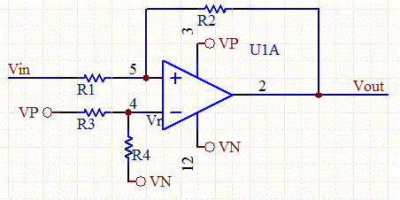
Hysteresis can be designed into a comparator circuit, by inserting a resistor from the output to the positive terminal of the comparator.
Computing the resistor values for a given high and low threshold voltage is a common engineering task when dealing with comparators.

The general expression for the reference voltage VR in terms of the output voltage, input voltage and resistors is as follows:

We can rearrange for the input voltage:

We want to determine the input voltage such that the positive terminal of the comparator is equal to the reference voltage for both cases when the output voltage has swung to the positive rail and alternatively to the lower power supply rail. These two voltages are the high and low threshold voltages of the hysteresis curve.


Given the above two equations, we can express either threshold voltage in terms of the other threshold voltage:

Thus, the resistor ratio can be expressed as:

and the reference voltage can be expressed as:

The design steps are as follows:
- Determine appropriate high and low thresholds of the hysteresis curve.
- Solve for the resistor ratio, and select R1 and R2.
- Solve for the reference voltage. Normally a resistor divider is used to set this voltage, but other methods can be used.
We've created a simple hysteresis calculator which computes the resistor values and reference voltage.

