Transformerless AC to DC power Supply
Disclaimer: These circuits use dangerous HV AC. Use at your own risk. We don't guarantee the accuracy of this information. In addition, we make no claim as to the conformity of these circuits to UL regulations.
It's often necessary to power a low voltage circuit such as a microcontroller with HV AC line current. For example, most fire alarms are powered this way. In these situations, a transformer is both bulky and expensive especially if the device is a consumer product. The solution is to use a reactance to limit the current, rectify the voltage with a diode, regulate the voltage with a zener, and use a large electrolytic capacitor to filter out the ripples.
The main disadvantage of transformerless supplies is that they don't offer isolation from the HV line and present more of a safety issue.
We present four circuits which use this principle and a calculator which determines the power capability for the circuit. These circuits are based on the www.microchip.com App Note AN954.See the application note for the equations upon which the calculator is based.

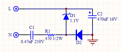
Figure 1 - Capacitive Transformerless AC to DC Power Supply, with common Hot.

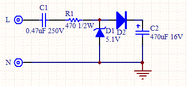
Figure 2 - Capacitive Transformerless AC to DC Power Supply, with common Neutral.

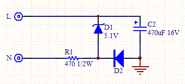
Figure 3 - Resistive Transformerless AC to DC Power Supply.

Figure 4 - Full Bridge Resistive Transformerless AC to DC Power Supply.
The circuits are essentially the same, the main difference is that the capacitive circuits use an additional series capacitor to limit the current. The bridge circuit presents full wave current to the filter. Table 1 shows the relative merits of each circuit.
| Supply Type | Pros and Cons |
| Capacitive | Higher cost than resistive, more efficient than resistive. The zero crossing is delayed. |
| Resistive | Lowest cost, least efficient. The zero crossing is not delayed. |
| Bridge | Highest cost, but highest current capacity and efficiency. The output voltage isn't referenced to line or neutral so TRIAC control isn't possible. |
Use a class X2 capacitor for C1 with voltage double the line rating. Double the returned power values for each component to give sufficient power margin.

