Voltage Summer Calculator
A common analog mathematical computation is to add several voltages:
Vo= V1+ V2.. VN.
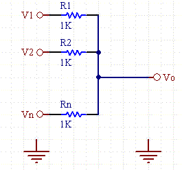
This is easily done with the following circuit.

Figure 1. Resistive Adder Circuit Schematic.
Because resistive circuits are linear an analog voltage summer circuit is constructed from one or more resistors combined at a node. Because of the law of superposition, the output is a sum of the individual input voltages scaled by the resistor networks. If the resistors are all the same value, then the voltage is the sum of the voltages divided by the number of channels.
The passive circuit results in an attenuation of each signal, so in common practice this circuit is often followed by an active gain element such as an OpAmp to restore the signal levels of each circuit.
Equations:
Vo= sum( Vn*(Rpn/(Rn+Rpn)) for n=1 to N
Rpn is the parallel combination of other resistors not including Rn
If all resistors are the same value:
Vo= sum( Vn)/N for n=1 to N

