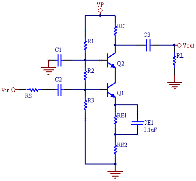
BJT Cascode Amplifier Calculator
This calculator computes bias voltage and current levels, as well as gain and frequency response for the Cascode amplifier.
The cascode amplifier has high gain and high band width. It overcomes the Miller capacitance limitations of the common emitter amplifier by using a second transistor as common- base current buffer. As a result it can achieve gain bandwidths orders of magnitude larger than the common emitter amplifiers. The only cost is that a second transistor is needed, and a higher voltage supply is needed so that the transistors have decent operating margins.
For the this cascode gain is set by the ratio of RC/RE2. To increase bandwidth maximize the sum of RE1 and RE2.

It should be noted, that in the real world, for frequencies above 2MHz, a second emitter follower buffer stage is needed to prevent loading of the output stage, and reduced frequency response. The capacitance from even a 1MHz scope probe will roll the frequency of this amplifier off at 2 MHz. To measure frequency response on a scope, measure on the output of the cascode through a buffer.
Equations
VB1= R3/(R1+R2+R3)
VB2= (R2+R3)/(R1+R2+R3)
VE1= VB1-VBE
VE2= VB2-VBE
VC1= VE2
VC2= VP - IC*RC
RB1= R3*(R1+R2)/ (R1+R2+R3)
IB*RB1 + IB*Beta*RE+VBE=VB1
IB= (VB1-VBE)/(RB1+Beta*RE)
IC= Beta*IB
gm = Ic/25mA
rπ=Beta/gm
If RE2 is zero ohms:
A= -gm*((RL||RC)*(R2||R3))/(R23+RS)*(rπ/(rπ+Rx+(R2||R3||RS)),
else
A= -(RL||RC)/RE2
Rx is typically10-30 ohms, we use 20 in the calculator.
fT= gm/(2π*(CBE+CBC))
f1= 1/(Rin*(Cbe+ 2*Ccb))/(2*π);
f2= 1/(RL*Ccb)/(2*π);
The lower pole is dominate:
BW= f1;

