LaserDrw Tutorial
By Tim Daycounter
This tutorial explains how to use LaserDrw a common stand alone control software for cheap Chinese laser engravers. This software is poorly documented, has a terrible user interface, and non-intuitive, but it works. We should consider ourselves lucky that the Chinese haven't figured out how to write user friendly software, yet.
You need a USB dongle to access the software. The software also can be plugged into Correl Draw, but we will only be discussing the stand alone software here.
The biggest conceptional problem with the software is that you can not cut vectorized lines, it can only cut out shapes. For example, suppose you want to cut a circle and so you draw a circle as a line. LaserDrw will cut 2 lines on the path, which is completely a crazy thing to do. You would think that it would just cut any line as a vector, but it doesn't. It only interprets the transition between black and white as a cut. Since lines have width finite, it cuts the white/black transition on one side, and then the same to the other white black transition. The solution then is to fill in your circle with a paint pour, then it only see's a single white black transition, and creates a single cut line. If you import a DXF,DWG,WMF file or other vectorized format directly, it will cut two lines, so you have to fix up these formats by bringing them into a paint program like Gimp, and then do a black color pour on all of the insides of the objects to be cut. If you have holes or other cut outs from the main body, these can be left white, and they will be cut out, since they have a different color than the main body. The color pour in Inkscape doesn't work great, so it's better to do with a rasterized image in a paint program like Gimp.
Using with Solidworks
Create a drawing in Solid Works with scale 1:1. Make sure that there is no sheet format, so delete it so that the page is white. In the tree, right click on sheet and select properties. Set the scale to 1:1 and set the sheet size to "Custom" and enter the drawing width and height in mm. File save as png. Then open the png file in Gimp or other drawing program. Use the color pour the "Bucket" icon, and fill in the shape with black. Use 600 DPI. Save and import into laser draw.Suggested Image Creation Software
The following two awesome open source programs are completely free to use:- Gimp - Use gimp for editing photos and rasterized images.
- Inkscape - Use Inkscape for vector graphics. Vectors or line art are used when you want to cut instead of engrave.
If you want a vector image for cutting rather than engraving, save the Inkscape image in EMF or WMF format.
Suggested File Formats
- gif - Use this format for monotone pictures, like text or logos.
- jpg - Use this format when engraving gray scaled photos.
- png - This didn't work when I tried it, the background was black. Perhaps I had an undefined background color.
- emf - Windows Meta-file - This is a vector format, and can be used when using the laser for cutting.
- wmf - Enhanced MetaFile - This is a vector format, and can be used when using the laser for cutting.
Menu Structure
The following image of LaserDrw shows the file menu.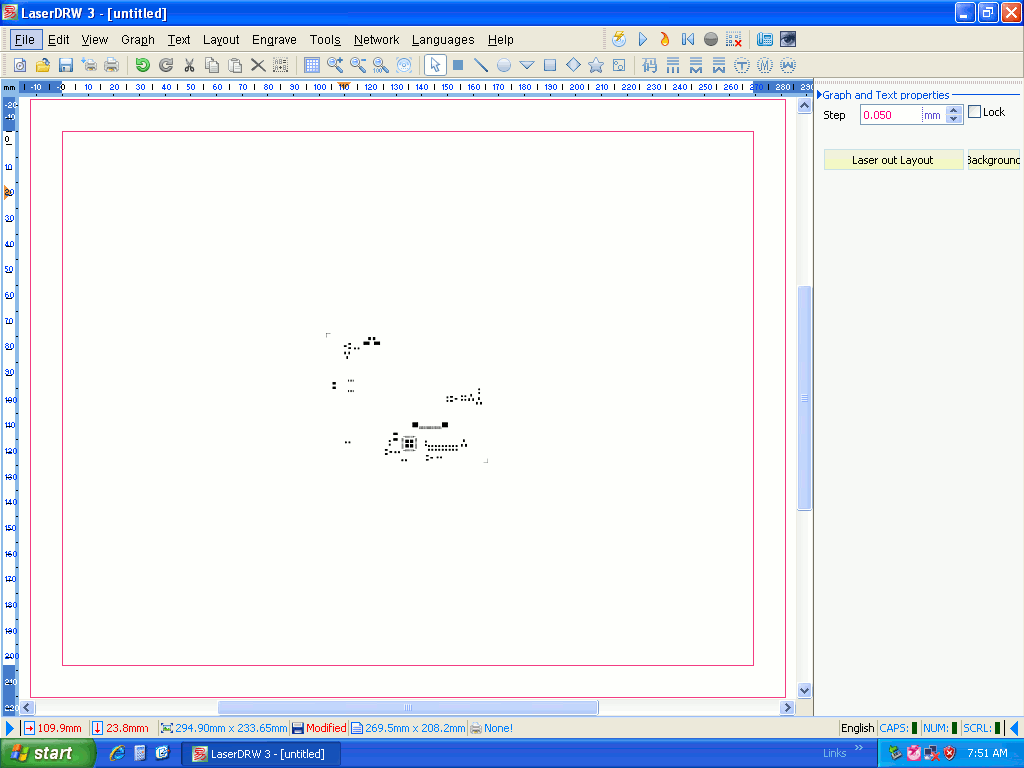
- File
- Basic Templates
- Custom Templates..
- New Layout
- Open - Use this to import your artwork files.
- Save
- Save As
- Save as Template
- Send to Print Layout - Print to the selected printer.
- Print Layout
- Printer Settings - Select a printer
- Device Initialize...
- Login Password
- Exit - Quit the program
- Edit
- Undo - Self explanatory.
- Redo - Self explanatory.
- Cut - Self explanatory.
- Paste - Self explanatory.
- Delete - Self explanatory.
- Clear - Self explanatory.
- Ungroup text - Self explanatory.
- Edit Text - Self explanatory.
- Bring to Front - Self explanatory.
- Send to Back - Self explanatory.
- Select All - Self explanatory.
- View
- Properties Panel - Turn on or off.
- Tools Bar - Turn on or off.
- Status Bar - Turn on or off.
- Ruler - Turn on or off.
- Scroll Bar - Turn on or off.
- Grids - Turn on or off.
- Background Color - This is important if your artwork is white, then you can set your background color to non-white so that you can see it.
- Maximize - Zoom such that artwork fills the screen.
- Normal- Zoom such that artwork is at 100%
- Zoom In - Self explanatory.
- Zoom Out - Self explanatory.
- Refresh Workspace - Redraw the workspace.
- Graph- Simple drawing shapes.
- Dot - Draw a pixel.
- Line - Draw a line.
- Ellipse - Draw a ellipse.
- Triangle - Draw a triangle.
- Rectangle - Draw a rectangle.
- Lozenge - Draw a diamond shape.
- Five Star - Draw a 5 point star.
- Bitmap.... - Allows you to import a bitmap into your project.
- Text
- Identifer
- Line Text
- Line Mongolian Text
- Line Arabic Text
- Arcuated Text
- Arcuated Mongolian Text
- Arcuated Arabic Text
- Layout
- Brings up the Layout Dialog Box
- Engrave
- Engrave - brings up the Engrave Dialog Box.
- Import Laser File
- Clear Laser Task
- Tasks Waiting
- Stop
- Auto Release Rail
- Release Rail
- Reset
- Device Initialize....
- Tools
- Export Bitmap... - Allows you to save your project as a bitmap.
- Install New Font... - Unknown functions.
- Export CNC file (G-Code) - Allows you to save your project as G-Code.
- Network
- Database... - This brings up a message box saying that the function is disabled for non-mainland Chinese.
- Upload Image... -This brings up a message box saying that the function is disabled for non-mainland Chinese.
- Languages
- Auto Select Default Language
- Simplified Chinese
- Traditional Chinese
- English - The fact you are reading this, means you want English Selected.
- Help
- About LaserDrw - Brings up software version information.
- Developer's Web -
- Mail to Developer -
- Download Templates - Unknown.
- Manufacturers Information - Doesn't do anything.
Click on your artwork to get the menu as shown to the right.
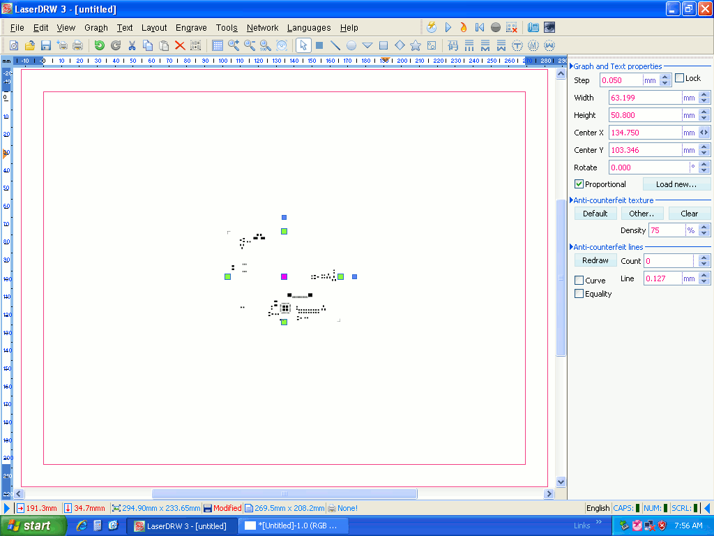
- Graph and Text Properties
- Step - Step size in millimeters.
- Width - width of imported image in millimeters. This should be the same as the document size that you exported from your drawing program.
- Height- height of imported image in millimeters.This should be the same as the document size that you exported from your drawing program.
- Center X - Center Relative to the stock.
- Center Y- Center Relative to the stock.
- Rotate - Don't use this because the program will freeze up. It's purpose is to rotate the artwork.
- Proportional - This should makes the Width and Height linked so that if you change one the other will change.
- New Load... - You can bring in new artwork with this.
- Anti-Counterfeit texture - I haven't deciphered these yet. I believe they are used to super impose another image.
- Default Button
- Other..
- Clear
- Density
- Anti-Counterfeit lines- I haven't deciphered these yet. I believe they are used to super impose another image.
- Redraw
- Curve
- Equality
- Count
- Line
Laser Layout Dialog
The laser layout dialog box has the drawing workspace values linked to the laser workspace values through the margin. So if you modify one, it will automatically modify the other.LaserWorkspaceWidth= Drawing Workspace Width+ Margin.
LaserWorkspace Height= Drawing Workspace Height + Margin.
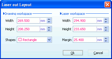
- Laser Layout Dialog
- Drawing workspace - This is really the stock size that you are cutting from, not the drawing size.
- Width - Width of the stock.
- Height -Width of the stock.
- Shapes - Shape of the stock.
- Laser workspace - These are essentially the stock size plus the margin. The origin of these coordinates is the current position of the laser head. The Drawing/Stock workspace is offset from the origin by the margin value for both X and Y.
- Height - Drawing/Stock height + margin.
- Width-Drawing/Stock height + margin.
- Margin- Offset from origin to stock size.
Engrave Dialog
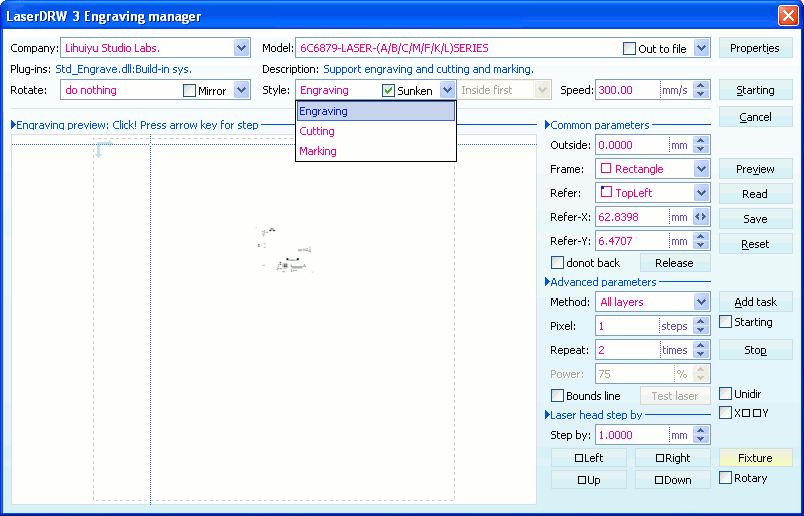
- Engrave Dialog -
- Company -
- Model -
- Rotate -
- Properties -
- Style -
- Engraving - This is for pixelated images. If sunken is selected, then the laser is turned on for black colored image pixels, otherwise, the laser is turned off for black colored image pixels, and turned on for white pixels.
- Cutting - This option will turn on the laser for following and cutting line vectors. A common problem that can occur is that the laser will mark thick lines twice. Keep the line width on the artwork to .025 mm, to avoid a double cut.
- Marking - This is similar to engraving with the sunken option selected.
- Speed - 16mm/sec is good for 1/8 inch thick acrylic
- Common Parameters -
- Outside or JoinGap - On some versions this is called "JoinGap" on other's it's called "Outside". Sometimes artwork will have small gaps between lines, and when cutting the laser will treat these as separate lines and briefly pulse off the laser for the gap. If the JoinGap is set to a non-zero value, then gaps smaller than this value will be treated as continuous, and the laser will not turn off between the gap.
- Frame - The shape of the stock.
- Refer - The zero reference of the stock relative to the machine's coordinates.
- Refer-X - The x reference of the stock relative to the machine's coordinates.
- Refer-Y - The y reference of the stock relative to the machine's coordinates.
- Do not back - Tells laser to not return to the origin when the task is complete. The laser stays where it is when it finishes. For multiple task jobs, this would be set.
- Advanced parameters -
- Method - This option is used for correl draw. Set to all layers for the stand alone.
- Pixel -
- Repeat -
- Power - grayed out. Most machines don't have computer controlled power. m
- Add Task - chain multiple tasks
- Starting check box - Start a job with multiple tasks
- Laser head step by - Jogging controls.
- Step by - Jog distance in millimeters.
- Left Button - Jog left by designated jog distance.
- Right Button - Jog right by designated jog distance.
- Up Button - Jog up by designated jog distance.
- Down Button - Jog down by designated jog distance.
- Starting Button - Start running.
- Cancel Button - Stop running
- Preview Button -
- Read Button -
- Reset Button -
- Stop Button - Stop running.
Machine Properties Dialog
