
40 Watt Laser Upgrade
We recently upgraded our Chinese laser cutter, with a new control board, and accessories. It originally had the Moshi control board with a six pin power connector, and the crappy LaserDRW software that is included with many Chinese laser cutters. We used it, in it's original state for the first few years, but the software was difficult to use, poorly documented, and not very flexible.
After several years it died. (More on that later.) We decided that, if we were going to fix it, we might as well upgrade it too.
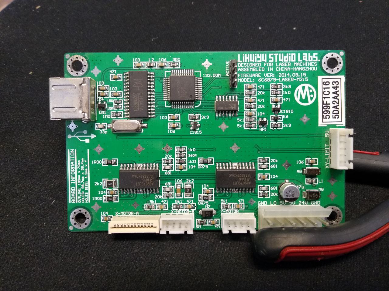
We searched for a new control board, and the best option we found was the Cohesion3D LaserBoard. It's basically a drop-in replacement, and required very little setup.
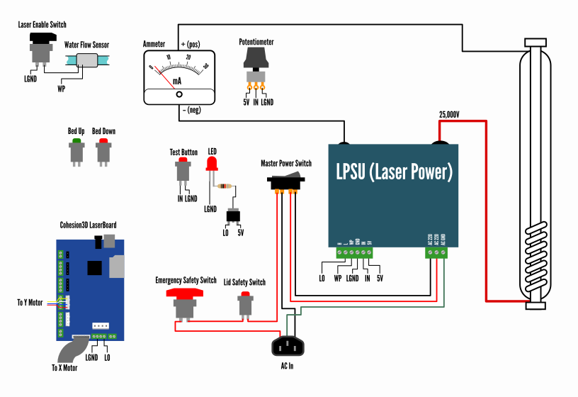
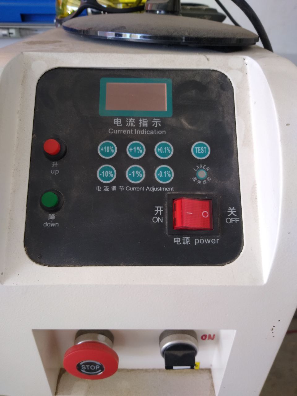
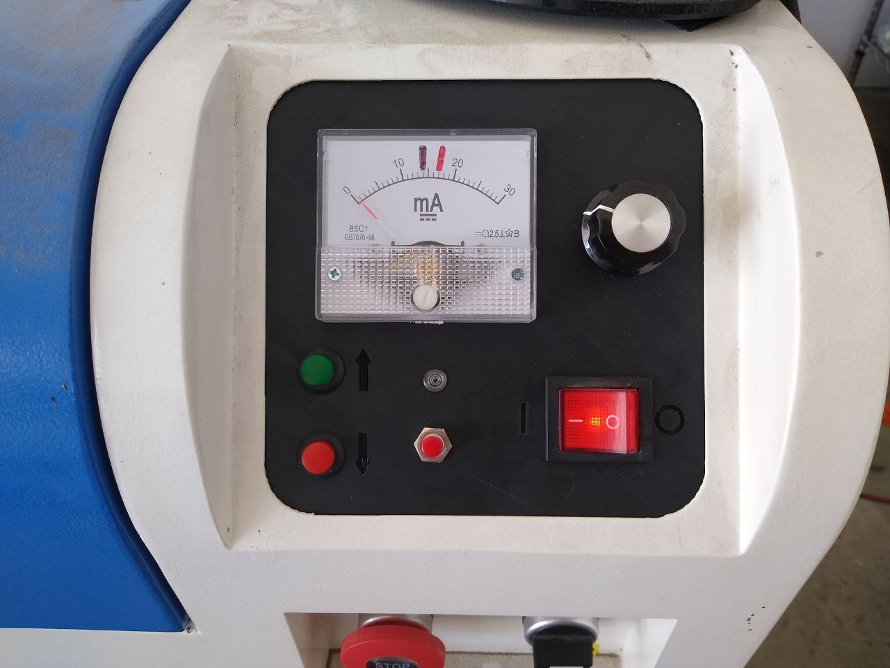
We also installed a few other upgrades. Cohesion3D recommended installing an analog potentiometer, and an analog ammeter in order to have finer control over tuning the laser's power. The original machine had a digital control panel, which was useless because it didn't have any feedback and wasn't tuned. If you entered a value of 100%, there was no way of knowing what power the machine was actually putting out. With the ammeter, you know exactly how much power the laser is putting out.
*Note* - Always make sure that the machine is unplugged before you work on it. Even if the power switch on the machine is turned off, there are live wires running through it, and you could easily be injured or killed.
The Laser Control Board
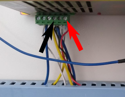
In connecting the new controller board, we had to cut the power connector from the old control board so that we could access the laser ground and LO lines. The LO line is the line that activates the laser. In our machine we are using the line that activates when it is pulled to ground, but some machines use the line that activates when pulled high. Be sure to double check yours. The LaserBoard doesn't need the 5V or 24V lines from this connector, so we left them alone until we could remove them from the system later, then connected the ground and LO lines to the LaserBoard screw terminals. On our machine the wiring was: RED = GROUND(?!), Yellow = +24V, Blue = +5V, and Black = LO, but yours will likely be different. We rewired ours to make more sense a little later in the process.
If you are going through this process yourself, note that your connectors and wiring will most likely be different than ours. We used the guides from Cohesion3D to figure it out. Our machine is a larger one, so we used this guide, and it had the six pin power connector, so we used this guide.
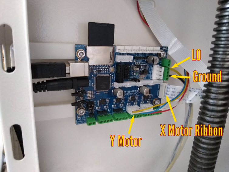
We connected the X and Y motors to the board according to the guide. The ribbon cable could only go one place, and the other connector connected to the "Y" connector on the LaserBoard, and that was it for the connections to the LaserBoard. We had to configure the settings for our machine on the SD card.
Once all of that was done, we put the SD card into the LaserBoard and powered up the machine. The X and Y motors started moving and homed the top left corner, but we couldn't get the laser to fire. We decided to look at the LO line and see if that was functioning as it should.
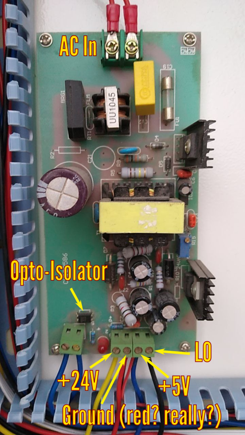
We traced it back to this board which turned out to be a power supply to convert wall power into +5V and +24V, as well as hosting an opto-isolator for the LO line. With the LaserBoard, we no longer needed the +5V or +24V lines and, since the LaserBoard has its own opto-isolator for the LO line, we decided to get rid of this board all-together. The only thing that it would have been powering was the small red positioning laser pointer on the head of the cutter, so we attached the 5V and Ground wires from that to the 5V and GND terminals on the big laser power supply.
We extended the LO and ground wires from the control board so that they could reach directly to the laser power supply screw terminals. While we were working on that bundle of wires, we went ahead and pulled out the wires for the +24V and +5V that were no longer needed, and also changed the original wiring around a bit so that the colors made more sense. We eliminated blue and red, and wired black to ground and yellow to LO on the big laser power supply, then made sure those connections were corrected on the LaserBoard.
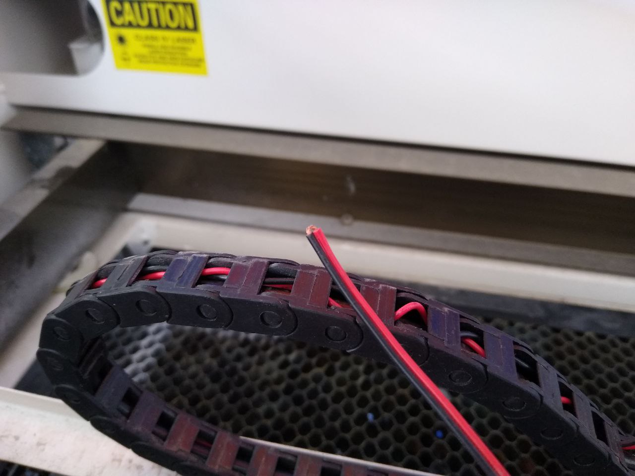
So now that everything was connected we powered it up again. The motors still worked fine, but the laser still wouldn't fire. We noticed that the red laser pointer wasn't lighting up, and decided to check the 5V lines with a multimeter. 5V was dead. So we powered down the machine and checked for a short. Sure enough, the 5V line was shorted. We found that the short had been caused by a break in the lines going to the red laser pointer. The wires had broken inside of the cable guide, right at the point where they were most bent when the machine was at rest. When they broke, they (of course) shorted to each other, which shorted out the 5V supply, and brought the whole machine down.
So now we knew why the machine had broken in the first place, but did the laser work? We ran new wires for the red laser pointer, powered up the machine. It worked great.
The Control Panel
We first had to design a new control panel to hold the new components. After carefully documenting the connections with photos, we disconnected the old panel and pulled it out. Using measurements from the old panel, we laid out a new one in CAD, and then 3D printed it.
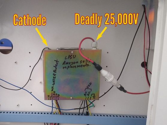
*Note* - The laser power supply outputs 25,000V and could easily kill you, so be careful that you know what you are doing, and also unplug the machine and allow it to sit for a few hours, or over night, to allow any internal capacitors to discharge.
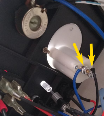
The ammeter should be connected in series with the cathode of the laser. On our laser power supply, the cathode wire is located here:
The Cohesion3D documentation great help. We cut that wire and soldered in an extension so it would reach the ammeter in the control panel, and connected the wires
The potentiometer was pretty simple. We just connected 5V to one side, ground to the other, and ran a wire from the sweeper to the IN connection on the laser power supply. This signal sets the output strength of the laser depending on the supplied voltage (0-5V). It is usually recommended that you use a ten-turn potentiometer for this part for maximum precision in adjusting the laser power, but we had a single turn 100K pot sitting around and decided to use that. It seems to do the job just fine.
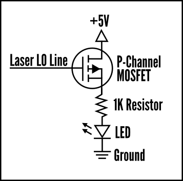
We wanted to have the laser light up the LED on the control panel when it fires, so we put a P-channel MOSFET on it and connected the gate to the LO line so that when that line goes low to activate the laser, it also turns on the LED. Here is how the connections went together:
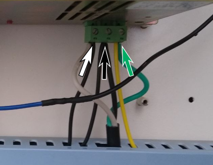
We then connected the test button to ground and the LO line, so that it would connect LO to ground when pressed, and activate the laser.
The laser cutter also has a movable bed, so we connected those buttons the same as they had been on the original control panel.
The last thing we did was to wire in a plug so that we could power the LaserBoard from inside the machine and turn everything on with one switch. We cut off the female end of a short extension cord and ran those wires to the AC power screw terminals on the laser power supply. In our machine the wire colors only occasionally indicate what they do, and in this case the two AC lines were both black. We traced them back to the source to figure out which was hot and which was neutral, but the power supply for the LaserBoard isn't polar, so it didn't actually matter, we just wanted it to be right.
At this point everything was connected, so we threw the switch, and, miracle of miracles, everything powered on and nothing caught on fire. The only mistake we had made was that we had hooked up the drain and source on the MOSFET backwards, so the LED was always on. we shut it all back down, fixed that, and it worked!
Finally
With the new board installed we can use better software to control everything. We got Cohesion3D's LightBurn software. So far it's been great. It's a major upgrade in usability, and functionality over the old software.
It took quite a bit of work, but the end result is a machine that we actually look forward to using, and will probably use a lot more often.