Voltage Controlled Voltage Source
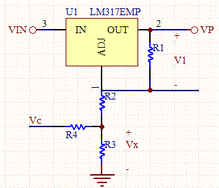
This circuit uses a single voltage regulator, but allows selection between two different output voltage supplies. A microcontroller can control the Vc input to the circuit, and pull it low for a lower output voltage, or a high for a second higher voltage.

Selectable Voltage Source Schematic
Circuit Analysis
When the control voltage VC is set low to ground, the circuit looks like a traditional voltage regulator circuit with R4 in parallel with R3 and in series with R2:
RB= (R2+R3//R4)= R2+R2*R4/(R2+R4),
and the output voltage is governed by the typical voltage regulator equations:
V1= R1*VpL /(R1+RB)
RB=R1(VpL-V1)/V1
However, the analysis becomes more complex with VC set to a non-zero voltage:
VpH= V1+V1*R2/R1+Vx
We have a multitude of free parameters so we can just set R3=R2.
Through superposition:
Vx= V1*(R2*R4)/(R2+R4)/R1 +R2*Vc/(R2+R4)
Thus:
VpH= V1+V1*R2/R1+Vx+V1*(R2*R4)/(R2+R4)/R1 +R2*Vc/(R2+R4)
VpL=V1+V1*R2/R1+Vx+V1*(R2*R4)/(R2+R4)/R1
Combining the two equations:
VpH= VpL+R2*Vc/(R2+R4)
R4= R2*(Vc-(VpH-VpL))/(VpH-VpL)
Let A= (Vc-(VpH-VpL))/(VpH-VpL),
so R4= R2*A.
RB= R2+A*R2^2/(R2+R2A)
R2= RB(1+A)/(1+2*A)
So the design methodology is to first design a standard 2 resistor voltage regulator, with 2 resistors. Then split the grounded resistor RB into three resistors, two in parallel with one in series. Then use the equations above to find R2, and then R4.
Note that V1 is usually around 1.25V.

